
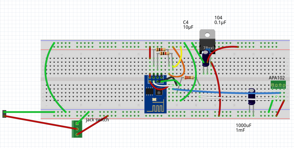
Smart Poi are based on the ESP-01. The circuit is shown here:
Here is the PCB – generated by Fritzing software:
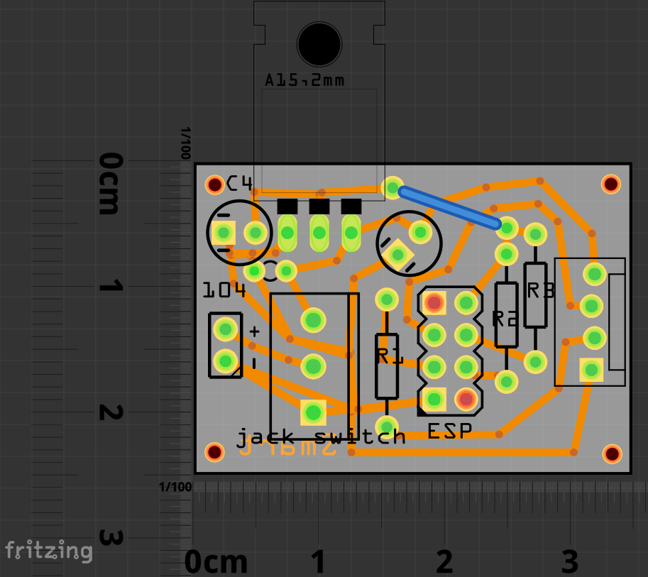
I have uploaded the Fritzing files to github here – you can modify or just print them yourself. The fab shop I used to print mine was happy just printing from a PDF and the result was great, but some shops only accept Gerber files, which Fritzing can generate too (they are in a folder on Github as well) – See my Fritzing Overview to get started with this great software
Parts list (per poi):
-

10PCS 1.2v NIMH AAA Battery 3A 1000MAH
Buy on Aliexpress -
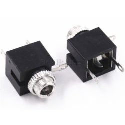
10Pcs Good Quality 3.5mm Female Audio Connector 3 Pin DIP Headphone Jack Socket
Buy on Aliexpress -
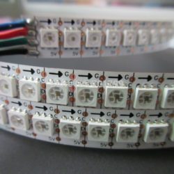
1m DC5V SK9822(Similar to APA102C) 144 px/m
Buy on AliExpress -
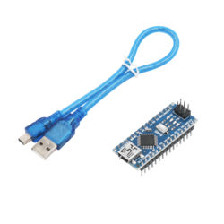
Arduino Nano 3.0
Buy on Aliexpress -
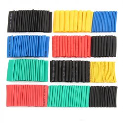
Assorted Heat Shrink Tubing
Buy on Aliexpress -
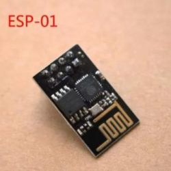
ESP-01
Buy on Aliexpress -
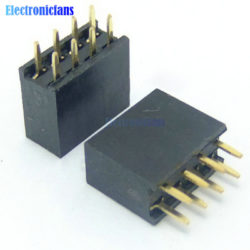
ESP-01 connectors
Buy on Aliexpress -
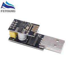
ESP01 USB Programmer
Buy on Aliexpress -
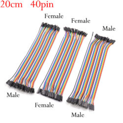
Jumper Cables
Buy on Aliexpress -
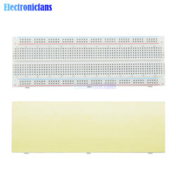
Large Breadboard
Buy on Aliexpress -
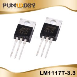
LM1117 3.3v regulator
Buy on Aliexpress -
Micro USB Cable for D1 mini
Buy on Aliexpress -
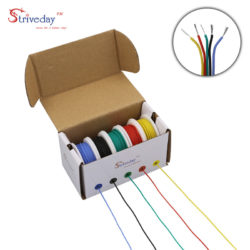
Thin Wire set, 5 colours
Buy on Aliexpress -
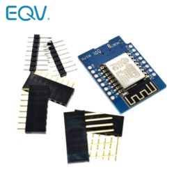
Wemos D1 Mini
Buy on Aliexpress
Additional Products:
Rigid plastic strip to stick the LED Strip onto PolyCarbonate/PVC-U tubemono mini jacks to use for switching poi on and off, and also for connecting to the charger. I connected two together in series to make a charging circuit for both poi at once. The charger I bought to charge NIMH batteries can charge up to 10 batteries in series. Nowadays I am using LiPo 3.7v which works great with as little as 500mAh (lasts for 1 hour at full brighness) or just put 2 together in parallel. When I started the project LiPo was not as good as it is now – it’s probably the best choice for batteries.
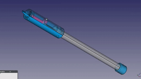
The tube:
Most poi you find on the market are housed inside a PolyCarbonate tube, however this is sadly unavailable in my country, so I found another product called PVC-U which is transparent PVC pipe and comes in all diameters. I have uploaded a CAD file which will help to demonstrate how everything fits together inside the tubes here. You need 3D CAD program like FreeCad to look at this.
It’s time to actually make these poi. This is not a step by step instruction list, as I made these a while back and can’t remember the exact procedure. Anyway you may be doing things a bit differently.
- Solder the components (see the Fritzing Repo for actual component info) and LED strip (stuck to rigid plastic strip) to the board. Don’t forget heat shrink to cover any exposed metal wires.
- battery pack (NIMH 4.8v or LiPo 3.7v) and Jack Switch gets soldered to the board (jack has 3 connectors, the pcb has 3 connections for this. The batteries need to be charged from a jack input to the female jack, and when plugged in the male jack disconnects the circuit from the batteries.)
- put together 2 sizes of pipe using screws and 3d printed connector pieces (see freecad github) – you could also use mouldable plastic
- need to drill a hole for the female jack connector in the side of the large tube. Put the screw end of the female jack connector through and screw it into place with the nut
- I used some bits of sticky backed rubber to keep everything in place inside the large component tube
- screw the two pieces together, glue on the other 3d printed pieces, however you can
- Oh I almost forgot: you need some sort of handle and string to spin it with
- unplug the mini jacks and your poi should come on.
Sign up for our update alerts: