
So far I haven’t gotten my new ESP32 based version of SmartPoi hardware working (re-named MagicPoi) – make no mistake, it’s coming but due to various reasons this keeps getting delayed. *ESP32 dual core is a game changer, that’s all I’m going to say here.
My ESP8266 based SmartPoi 36 and 72px poi are still going strong, on their third battery (now Lithium). So I got bored recently and instead of working on the new poi I had another look at SmartPoi Arduino code and remembered the “Hidden Feature” – Router Mode!
Activating Router Mode
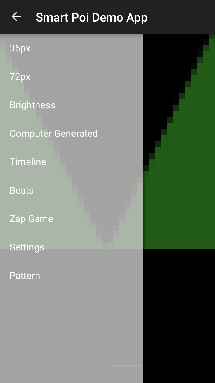
First of all, make sure you have the latest firmware. This is because the older versions may not include the fail-safe I built in. Remember that “Main” and “Auxillary” poi – and number of pixels – need to be set in code, before uploading. So in the SmartPoi app there is a menu entry called “Settings” – with Pattern and Channel fields as well as Router settings. Fill these in, using your own router settings to guide you. My address is 192.168.8.78 with Address2 79 but your router may be 192.168.1.xx or something completely different – the last numbers are for the fixed IP on your network, please consult the router options for available addresses on your own network.
Once you press “Send Request”, nothing happens. That is for a reason, it was an experimental feature and I didn’t want to brick anyone’s poi if they accidentally put the wrong Router or Password.. In order to activate the setting you have to go to a browser (on a device connected to the poi Access Point) and put in http://192.168.1.78/router?router=1 and then http://192.168.1.1/router?router=1
First the “Auxillary” poi (78), then the “Main” poi (1) please or it won’t work! At your own risk! You may need to try again if it doesn’t work.
What this does is set the poi to start up 50% of the time in STA mode – connected to your router with the static IP address you configured with “Settings”. Every time you switch the poi off and on again it changes, AP mode then STA mode and back again. Make sure to keep the 2 poi in sync, that is on the same startup mode as each other!
Both Poi will show a green . . . . . indicator when attempting to connect and fast green ……. when connected. If you see green dots going up slowly for ages it means it’s not connecting and the Router and Password need to be checked (in AP mode with the app)
What is this for?
AP mode is simple – your phone connects to the poi direct, no router needed. I have noticed, however that the AP signal is pretty weak on the ESP-01 so using a router could help reliability.
Also, ESP-01 AP mode can only connect 4 devices at a time – including the phone, so that’s 2 pairs of poi and controller max. With a router connection you could have a lot more.
Finally the Router connects to the internet. This is helpful because I am moving all of the functionality to the cloud (sorry) mainly due to being sick of Google changing things for Android developers all of the time – breaking things really. It’s too frustrating so I’m moving everything to the cloud. The Offline mode remains the same.
My SmartPoi demo app doesn’t work anymore!?
Yes I haven’t had a chance to do anything with the Router Mode yet – the Android code doesn’t know about your new STA mode IP address. You can use the C code from the circusscientist site here with the new IP address for example: https://www.circusscientist.com/pov-wifi-streaming-with-c/
To switch off the Router option just do the following in a browser connected to the poi AP (poi in AP mode so not connected to your router) http://192.168.1.78/router?router=0 and then http://192.168.1.1/router?router=0
The SmartPoi Router option will soon be accessible from the main “MagicPoi” site, with downloads of your offline images (72px only) direct from the browser, control of functions, and more!


 into this: