Just a quick note about some updates – some done and some to come.
I really like the SmartPoi Downloader idea, so I am going to be upgrading this to include downloads of the Smartpoi-js-utilities and associated Android app as well as automatically updating the data folder with the right size compressed images (currently they are 72px by default). Soon it will be a one-click affair to get up and running with Smart Poi!
Speaking of Smartpoi-js-utilities, I am making this more user-friendly, now the number of pixels is fetched from the poi you are connected to. I also added some UI updates, check out the github for changes, more to come soon (give it a star while you are there, why not?). Please make sure to get the latest SmartPoi firmware at the same time – from github or the new SmartPoi Downloader webapp(you can tell I like it because it’s got https).
Magic Poi has a new feature – Timelines! I went a bit overboard with the css – check out the video below:
Well.. It kind of mixed everything up and confused some things but that is possibly not helped by the input. I did like the format, though, and I’m used to robot voices – check out the hacker news recap for a great example.
Also, who doesn’t like flattery? These guys went on for +10 mins about how cool my project is!
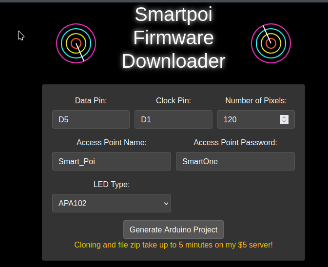
I made a Flask app from scratch using Aider – the AI coding assistant – and FREE LLM’s.
This is for the SmartPoi Arduino Firmware project – POV Poi, now easier than ever to use, just add your details in and download the custom Arduino sketch.
If you don’t have a big budget to pay for ChatGPT or Claude access it turns out AI coding for free is surprisingly effective. I generate a Flask app from scratch – all the way to deployment – using only free models. I also briefly compare some of the best free ones.
YouTube video of the Aider developent process:
Aider with FREE LLM’s
Some notes:
The free LLM’s are rate limited, on OpenRouter at least – so they take longer to load, and do make mistakes sometimes.
Claude 3.5 Sonnet is apparently the best?
Thinking of trying Aider for yourself? Check out IndyDevDan on YouTube first: https://www.youtube.com/watch?v=QlUt06XLbJE – here he explains the “advanced AI workflow” nicely.
Thanks to my new Patreon supporter Flavio I will be trying the paid version on the SmartPoi and MagicPoi code bases very soon
Note: While recording I forgot the name of the best paid LLM for coding: Anthropic’s Claude 3.5 as of record date. Join my patreon to help pay for my AI addiction and subscribe to the channel for more video’s!
UPDATE:
I am getting the best results lately from aider –model gemini/gemini-1.5-pro-exp-0827 – currently free with sign-up to google.
TLDR: Magic Poi Alpha is getting test circuit boards, new firmware which works with the new web service and development is being accelerated by AI. At the end I ask for money to fund the AI coding assistant – via my Patreon Account.
Major updates to the Magic Poi project:
HARDWARE:
ESP32 S3 chip
Buttons
2020 size LED’s for more pixels
Lithium battery
Full housing re-design
FIRMWARE:
OTA programming
Dual Core with FreeRTOS background processes (downloading images won’t interfere with display)
Streaming from web functionality
Full integration with magicpoi web service API but works offline
There have been some challenges – recently I found out that the new ESP32 boards I bought aren’t even fully supported by PlatformIO – but I found a way to work around that.
Ultimately I want MagicPoi to work seamlessly. Add your friends on the web dashboard, create some timelines and push a button on your poi to sync everything up.
Hardware:
The first test board is coming out soon. The design is finished, using EasyEDA. We will be sending the board for production by JLPCB in the very near future – look out for an update.
After that it’s on to the poi body full re-design and finally Indigogo when you will be able to purchase the very first Magic Poi.
You can help!
If you want to be a part of MagicPoi development and the road to the Alpha production line, you can. I have started a Patreon to fund my AI dev tool and services addiction* as well as web hosting costs** – until we have something to sell that is. A few dollars per month from you would really help make this thing go faster. Also, anyone who signs up will get some exclusive discounts on the finished product.
*Go check out Cursor IDE and also the open source Aider they are so worth it.
**I’m spending $25 per month on hosting, $20 per month on AI coding tools and of course my friends over at EnterAction are putting up their own money to do the prototypes.
Feel free to reach out to me and don’t forget to subscribe to the magicpoi mailing list if you haven’t already.
I recently purchased a new board, the ESP32S3 Super Mini. That’s an S3 dual core version of ESP32 on a tiny yet powerful board.
The problem
The issue was that this board wasn’t working right – I had my code all set up (the new “Alpha” version of Magic Poi firmware – not published) and parts of it ran great for testing in Arduino IDE but as soon as I ported to PlatformIO it wasn’t compiling.
The real problem
It turns out that ESP32 S3 Super Mini and many newer ESP32 boards are simply not supported any more in PlatformIO. In fact, anything that relies on Espressif Arduino framework > version 4 is out of luck – as far as I can tell the owner of PlatformIO had a falling out with Espressif (business? personal? no reason at all?) and now they don’t support the new versions which work great on Arduino by the way (now version 6.something) Here is the issue on Espressif arduino-esp32 github: https://github.com/espressif/arduino-esp32/pull/8606#issuecomment-1805781410 for reference.
A very smart and intrepid PlatformIO user, Jason2866 made a fork of the PlatformIO Arduino Espressif base and put it here, with instructions on how to use it – and he updated it on his own to use the latest arduino-esp32. After some light editing and moving stuff around (including accidentally putting GND into +5v and vice versa – thank you Super Mini board for not blowing up) everything is now working. The Magic Poi project moves forward!
Ever had your computer crash and had to re-install the OS, then restore all of your projects one by one, only to forget about an important file and re-do all of the work?
I did the test firmware for Magic Poi Lite 7 months and one Laptop crash ago. Today I went to upload the firmware I worked on all last week and it turns out I already have a GitHub repo set up – for the same project – which I forgot about.
Basically it fetches a list of files from the poi and then fetches each compressed binary file in the list, decompresses them and displays the resulting images. Up until now the only way to see what was actually on the poi was to spin them, so this is definitely an improvement. This is all done using the SmartPoi AP – no internet access required!
Any day now* I will be upgrading my poi to work with ESP32 but until then I’m still trying to make the ones I use in my shows better!
*I am aware I have been saying this for a while now🙂
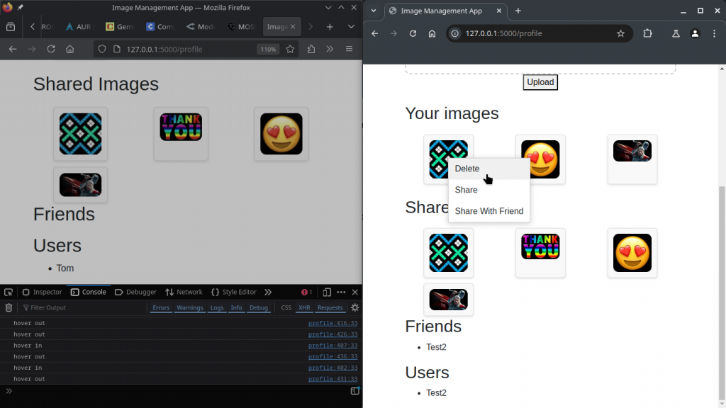
I wrote some new code, so now you can upload offline images from a web browser! Finally the (old) poi can take advantage of the hack I did to have up to 52 offline images displaying.
Then clone this repository here https://github.com/tomjuggler/SmartPoi-js-utilities to your computer and follow the instructions in the README. It all runs in a web browser, nothing to install or download (currently tested working on 36px poi using Firefox browser).
Thanks to Andreas for giving me the reason to make this – look out for updates to the SmartPoi project, more control from a web browser coming soon. I think I already mentioned this in my previous blog post – I am a bit tired of fighting with Android!