Smartpoi is open source

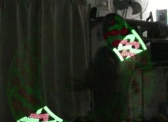
I am working towards opening up the whole thing, hopefully I can get some productive feedback this way. However, to make something for yourself is one thing, to share is another. Lets just say the code is not ready to be shared. #messyprogrammer a lot

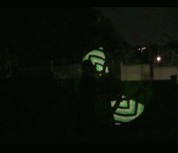
In the meantime here is a simple POV example on github which will work for esp8266 connected to an APA102 144 strip (36 LED’s only for testing). Don’t forget to add a cap between +5v and GND.

SmartPoiOffline

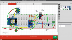
Here is a test board I made up, you don’t need the whole lot, just one of the esp breakouts and the LED strip. Here I have 2 controllers (only one on at a time!) and also a voltage regulator, and accelerometer as well.

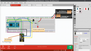
In case you are wondering, the Esp-01 is connected to the breadboard by this method: http://www.instructables.com/id/Making-ESP8266-01-module-breadboard-friendly/

Simply put, you remove the plastic pin spacers with plyers, and now the pins are bendable to a more breadboard friendly configuration. No soldering needed.

Breadboarding Stage

Test breadboards finished, populated and tested working (with LED’s) here.

First the RF controlled laser (nRF24L01+). couldn’t find any lasers in Fritzing parts 🙂

We plan on controlling more than 10 lasers, so made 4 of these on breadboard for the software test:


Next up is the Bluetooth Controller. This pairs via bluetooth to an Android app which then sends the correct on/off signal via RF to the Lasers.

Currently the signal is sent to all the lasers simultaneously, then they work who it was for according to what was sent. The signal is actually sending RGB codes, in case I want to add RGB in later, so should look like this: 1 255 0 0 means laser number 1 is on (or RGB led set to RED 255 full on).

1 0 0 0 would mean laser 1 off. The last 2 numbers are redundant but I am hoping to re-use the code for RGB LED’s at some point, so a couple of wasted bytes is nothing.


Speaking of wasted bytes, there is another byte for the node (the RF24 Arduino library uses the concept of nodes – up to 6 connected to each signaller)

I wanted to have more than 6 lasers and noticed if you define 2 nodes with the same address they both receive the signal. I am pretty sure that if 100 lasers are defined with the same node address they will still all receive the same signal. Then the software I have written can distinguish which laser is supposed to turn on, by parsing the 2nd argument. I am keeping the node byte for possible multi-setups.

Here is the full transmitted protocol:

Node

Laser

Red

Green

Blue

– using RED value for on/off on the one laser I have connected on the receiver side.

-soon we will have multi-lasers!

INTRODUCING SMART POI

Smart Poi, a new type of graphic poi+


=


Does everything those other graphic poi can do plus:
Wirelessly transmit images and patterns direct to your spinning poi
Receive SMS messages direct to your spinning poi
Synchronize instantly with multiple other poi
Timeline and Sequence mode control from Android app
Unlimited number of pictures
Animation and *new* dynamic computer generated patterns
Beat responsive

UPDATES:

Sign up for our update alerts: