Here is something you can do with multiple poi sync. All poi are now part of one address system. Easy to send some pixels through inside a loop.
Here is something you can do with multiple poi sync. All poi are now part of one address system. Easy to send some pixels through inside a loop.
First things first, have you tried setting up the breadboard test circuit?
Does the SmartPoiOffline sketch upload correctly, and display on 36 connected LED’s? (if you have a longer strip and don’t want to cut it, that’s fine, the rest will just be blank)
Ok it’s time to try streaming pixels.
First load the SmartPoiBasicStreaming sketch to your microcontroller. Right now this is only being tested on the D1 mini, but should work on any ESP8266 board.
The SmartPoiBasicStreaming_UDP_Send program works on PC or Android, you just need Processing IDE with Android Mode installed if you want to do Android.
First, switch on the D1 Mini with LED strip attached. Wait for the led’s to finish cycling their startup pattern, then you need to use the wifi settings to connect the device (PC, Android*) which is running the processing code to the Smart_Poi_2 access point. The password is for this test is: “bluefire”.
*Note: since Marshmallow version, Android has had a nasty “captive portal” detection which refuses to connect to AP’s unless they are able to access the internet. I understand why they did this (security), but without root the only workaround is to put the device in Airplane mode, then switch on WiFi while still in Airplane mode, and connect from there. The annoying notification should be ignored, as there is an option to “never connect to this network” in there somewhere and it will trip you up. I should probably do a post about this. Just swipe it away, don’t click!!!
Once connected, start the program. Welcome to the world of streaming poi.
A couple of notes: the test program is not POV, it’s an animation (cylon effect) as this is easier to see on a breadboard. I have a complicated program to send images to the poi which are seen only when they are spun, however it’s easier right now to just start with a simple app for testing.
This program does demonstrate one advantage of streaming as opposed to rendering purely on the poi – that is control. It is trivial to change the colour from the random colours I have chosen to any you could wish. I had another version of this program with three knobs which can change the R, G, B values being sent. You could do a curve instead of straight lines, make the line fatter or thinner, slower, faster, and much more.
Have a go, and let me know what you think. Coming soon: more POV poi shenannigans!
The esp8266 is an amazing chip. On my poi the Master* poi creates a wireless access point which the Slave* poi connects to – and Android app connects as well, in order to transmit images. No router needed, just switch on poi, 2nd poi connect automatically, connect phone and start sending pictures.
*I have designated these names, for descriptive purposes.
There are limits, however. The ESP chips have a limitation of 4 connected devices per access point device. If you want more devices talking to each other you need a Router to handle the traffic.
This is fairly simple using arduino examples but it brings up configuration issues. I wanted my poi to be able to be used in standalone as well as Master-Slave-Android configuration, and now Router-Multiple-Poi-Android as well. A few settings are in order.
The first option, standalone poi without wireless, I configured directly in the loop() of code. If no wifi signal has been received within the last 5 seconds the poi switch to backup images. Great, if my phone’s battery dies the show still goes on.
The second alternative (Router) is a bit harder to organize. First, there is a limitation where the chip has to be told if it’s in Access Point mode or not on boot. Ok so that’s a setting. Then we need to know what the static ip address is (hard coded but configurable via web interface) so that we don’t conflict with other poi. Also, once you are in Router mode, what if there is no router?
Right now, my poi check a web configurable EEProm switch on boot first, for Router mode on/off. If Router mode is on, the poi enter connect mode. If, after a certain amount of time, the router is not found, the poi restart in Access Point (master-slave-android) mode. However, upon rebooting again they revert back to Router check, so one has to manually set back to Access Point only mode if required.
I need a diagram here to really show what’s happening.
The problem came in if the router wasn’t configured correctly, or was simply not available, the poi needed a reliable way to get configured. My poi get configured by web interface (local network, no cloud) so AP mode was needed by default in case things went wrong.
Here is the note from my code:
//to activate in browser: http://192.168.1.78/router?router=1
//to deactivate: router=0
So I just type it in the browser on my connected Android or PC and the poi are set. I will assign this to a button on the app at some point.
Currently the only option for multi-poi is to send the same image to all poi simultaneously (only 3 pairs, that’s all I have). This looks great, but there is much more to do obviously. Just a matter of code
Time to go play a bit with the toys…
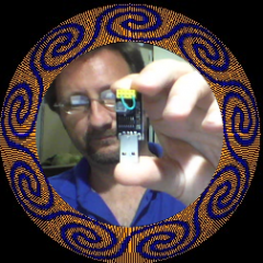
It’s really hard to photograph these fast moving, flashing poi.
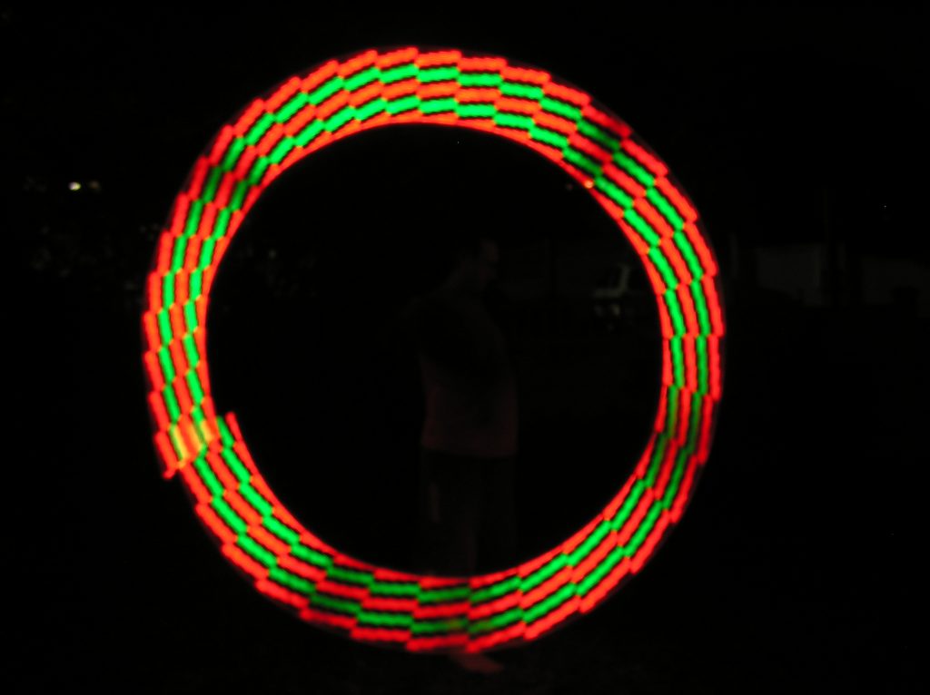
Here are some of the backup images (36px)


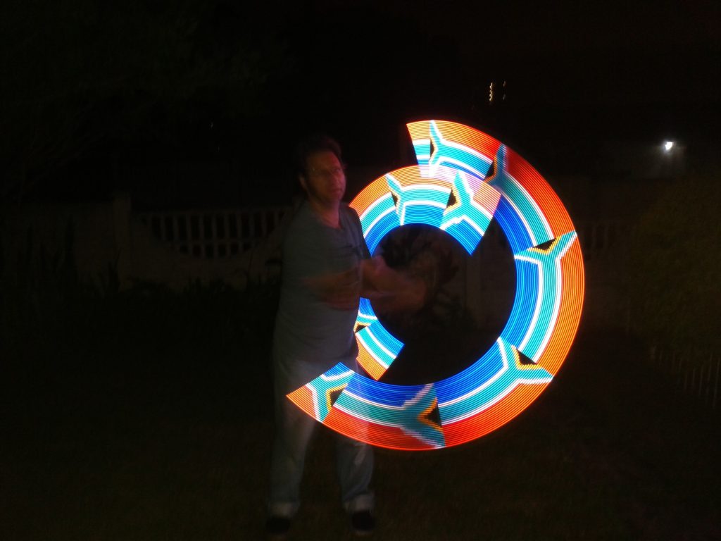
Here are some images being streamed wirelessly (36px):


Although the Smart Poi is based on ESP-01 for size reasons, I find it easier to use the excellent D1 mini for testing. Here is the basic setup:
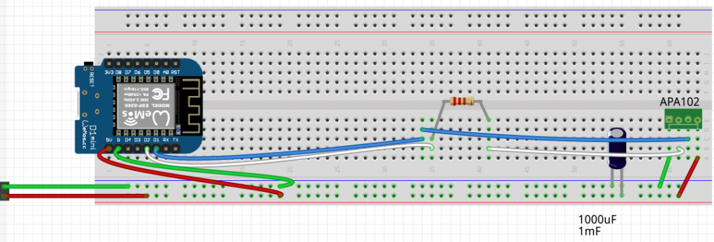
Notice that the D1 mini is powered from a battery source (4 x NiMH AA in series). This is not entirely necessary, you could get away with plugging in the D1 mini via USB, and connecting the APA102 strip to the 5v pin. The problem comes in when the LED strip starts drawing too much power, you will have dropouts in Wifi connectivity, or wdt resets and won’t know if it’s the code or just power.
Use the offline code from my Github repo to get started:
This code works fine on other Arduinos as well as ESP8266 chips. Just change the pins.
In order to try generate some interest I have started a project on the awesome Hackaday website: hackaday smartpoi project link
I will also be discussing elements of the programming and hardware on the new Processing forum: my activity on the new processing forum
and also the Arduino forum: arduino website forum
I am going to be busy!
Living in Africa is absolutely analagous to living in the old wild west sometimes. Just driving to work here can be a life threatening proposition some days. Protests, cash-in-transit heists, blown up ATM’s, hijackings and street beggars at every traffic light all threaten to disturb ones peace at any moment.
A bit like running Android on your phone really. That is unless you are up to date with the latest patched version. Which runs on precisely two devices as far as I am aware. The rest of us are left to make shift in yesterday’s abandoned OS graveyard, where the bad guys have their playground.
Privacy concerns? First world problems! Just be thankful that nobody screen captured your banking app today – while slowly cooking your phone casing with illicit cpu bitcoin mining cycles.
From a development perspective the OS is no better, a dictatorship with a fickle overlord. Time to change your code again, unpack and repack the activity car, it’s an API roadblock. Pay the play store compliance tax now or try your luck on the sideloading second economy, where your cloned apps beg at the same alternative app store intersection as you, with a flashy ad platform sign held high.
Gotta love Android. It’s the wild west out here. Android for Africa!
Two emulators are featured here, the first takes all images in a folder and shows them in sequence, as they would look on the spinning poi:
The second program receives RGB values from serial connected poi chip and displays on screen. This is showing what is actually being sent out to the LED strip, useful for testing – I was getting a bit tired of spinning the poi whilst programming them and the Android transmitter app at the same time.
The image below is of the computer generated default offline patterns, but if wifi sent images are available it looks somewhat similar to the above. Colour is not yet optimized.
For the serial sending to work on the poi, a fairly large change in code is needed. The serial necessarily slows everything down drastically, so it’s for testing only.
The ESP-01 are so cheap and versatile, you just have to use them. (Get one on Aliexpress for just $2 here: http://s.click.aliexpress.com/e/kNB84VvO) In the couple of years using these amazing cheap powerful chips, I have had my share of problems. Here are some big ones to avoid:
Problem: The programmer doesn’t work all the time.
Solution: Increase power. I use a cheap usb interface like this one:
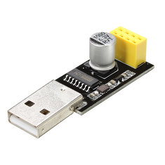
You can buy one on Aliexpress here: http://s.click.aliexpress.com/e/E7AiIOhw
First of all you need to know that you can’t just plug the ESP-01 module into the handy header socket and press upload on the Arduino IDE. You will get an error, as the ESP-01 needs to be put into programming mode. I did this by shorting the GPIO 0 and gnd with a wire. The ESP-01 still plugs in.
Now Arduino can upload! Unfortunately I was having intermittent “unable to upload” errors even after this hack, and a new batch of ESP’s from a different supplier barely worked at all. Something else had to be done. Adding a breadboard power supply did the trick, unfortunately with the addition of 7 wires and a breadboard, as well as an adapter for the ESP-01 and a switch to toggle programming mode…
*Update: you can ignore the above, nowadays I just click on upload and quickly unplug/re-plug the esp-01 (unplug the 8 pin header, not the usb!). Seems to do the trick!
Problem: Blink sketch says it’s uploaded but LED doesn’t blink.
Solution: After checking the pin numbering and seeing some possible related issues on a google search, I checked out the Arduino ESP8266 settings.
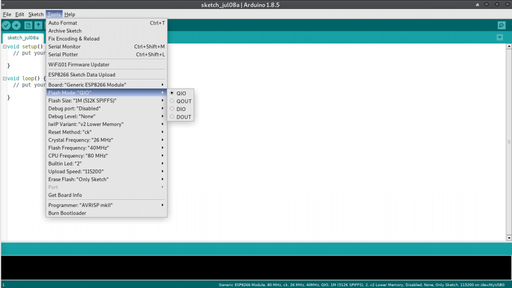
It turns out that all ESP-01 are not made equal. Most come with 1Mb flash but the type of flash (?) and the way it’s connected can vary. Hence the “flash mode” option. In my case, after extensive testing, DOUT was the correct choice. The LED blinks again.
Problem: After ESP8266 tool update, the dreaded WDT reset happens after a few minutes (time depends on what the program is doing)
Solution: After some testing I found it was a memory overflow causing the issue. This led me to refine the google search and finally I found a relevant bug on github, to do with LwIP (the wifi firmware?). Here is the setting in Arduino:
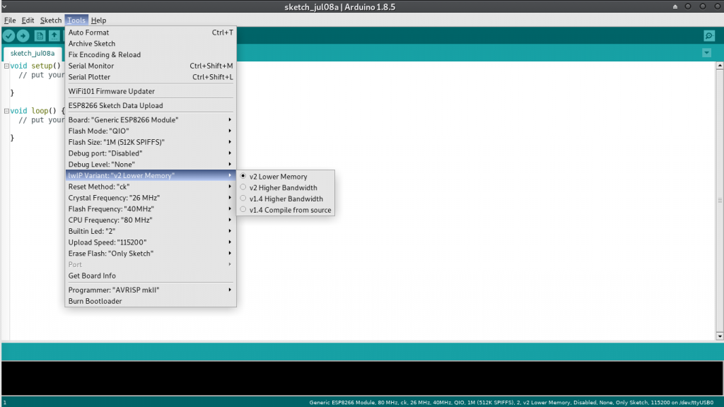
Changing to LwIP v1.4 Higher Bandwidth worked for me… It’s possible that this bug has been fixed by now, but I am sticking with the working version at the moment.
To summarize, ESP-01 is a bit tricky to program, there are so many variables in programming it, however they are so small and cheap – and despite many mistakes I have yet to brick one of these. I guess it’s worth the hassle*.
*UPDATE: CHECK OUT MY SMARTPOI PROJECT, made with the ESP-01 and APA102 LED strip.