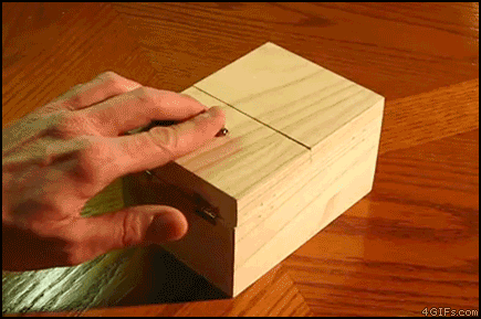
Tech used: FastMCP (Python) Arduino Uno (Serial) and Cline for VSCode (MCP Client), with DeepSeek Reasoner as the LLM – massive overkill just to turn on an LED!
This project was built using Aider – pair programming in your terminal. https://aider.chat/
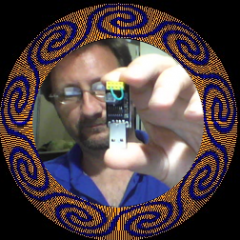
Check out the demo video where I tell the AI to turn on my LED – all done from Cline agent inside VSCode!
I had a fun few hours last week troubleshooting my “finished” SmartPoi firmware – which somehow decided to not do the one thing it really needs to do, connect to WiFi.
Turns out that in an effort to make everything more efficient I removed all of the delay() statements and gave the WiFi part of the microcontroller software no time to execute!
A simple yield(); in the main FastLED display loop sending image data to the LED’s solved the problem. So remember, don’t forget to yield.
I made a Flask app from scratch using Aider – the AI coding assistant – and FREE LLM’s.
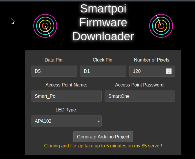
This is for the SmartPoi Arduino Firmware project – POV Poi, now easier than ever to use, just add your details in and download the custom Arduino sketch.
If you don’t have a big budget to pay for ChatGPT or Claude access it turns out AI coding for free is surprisingly effective. I generate a Flask app from scratch – all the way to deployment – using only free models. I also briefly compare some of the best free ones.
YouTube video of the Aider developent process:
Aider with FREE LLM’s
Some notes:
The free LLM’s are rate limited, on OpenRouter at least – so they take longer to load, and do make mistakes sometimes.
Claude 3.5 Sonnet is apparently the best?
Thinking of trying Aider for yourself? Check out IndyDevDan on YouTube first: https://www.youtube.com/watch?v=QlUt06XLbJE – here he explains the “advanced AI workflow” nicely.
Thanks to my new Patreon supporter Flavio I will be trying the paid version on the SmartPoi and MagicPoi code bases very soon
Note: While recording I forgot the name of the best paid LLM for coding: Anthropic’s Claude 3.5 as of record date. Join my patreon to help pay for my AI addiction and subscribe to the channel for more video’s!
UPDATE:
I am getting the best results lately from aider –model gemini/gemini-1.5-pro-exp-0827 – currently free with sign-up to google.
I recently purchased a new board, the ESP32S3 Super Mini. That’s an S3 dual core version of ESP32 on a tiny yet powerful board.
The problem
The issue was that this board wasn’t working right – I had my code all set up (the new “Alpha” version of Magic Poi firmware – not published) and parts of it ran great for testing in Arduino IDE but as soon as I ported to PlatformIO it wasn’t compiling.
The real problem
It turns out that ESP32 S3 Super Mini and many newer ESP32 boards are simply not supported any more in PlatformIO. In fact, anything that relies on Espressif Arduino framework > version 4 is out of luck – as far as I can tell the owner of PlatformIO had a falling out with Espressif (business? personal? no reason at all?) and now they don’t support the new versions which work great on Arduino by the way (now version 6.something) Here is the issue on Espressif arduino-esp32 github: https://github.com/espressif/arduino-esp32/pull/8606#issuecomment-1805781410 for reference.
A very smart and intrepid PlatformIO user, Jason2866 made a fork of the PlatformIO Arduino Espressif base and put it here, with instructions on how to use it – and he updated it on his own to use the latest arduino-esp32. After some light editing and moving stuff around (including accidentally putting GND into +5v and vice versa – thank you Super Mini board for not blowing up) everything is now working. The Magic Poi project moves forward!
My K8 Prophecy clubs have reached the end of their tether. After 8 years of use! First of all, many thanks to K8Malabares for their excellent equipment. Most smartphones won’t last that long (except for my Samsung Galaxy S2, which still works). If you need juggling equipment you can’t go wrong with K8. I have some of their non-LED equipment as well and it’s just as good.
Upgrade
About six years ago I did an experiment – to see if I could emulate the K8 IR code on an Attiny85 chip. I knew they used that chip, or possibly the Attiny45, because one of my clubs was faulty and I opened it up to have a look – K8 sent a replacement, by the way, talk about great customer service!
Now that my balls and clubs are not working anymore, due to the battery reaching end of life, it’s the perfect time to test out my new code. Luckily K8 didn’t solder their chips, instead opting for a convenient chip socket for easy replacement! I made some updates to the code, adding new functionality and colours. (K8 have also done an update since I bought my equipment) The most important, for me, was adding a timeline record and playback. This means that I can record the timed colour changes for my entire show into the chip via IR remote, and play it back (in time with the music) by pressing a single button. This is similar to how Aerotech Ultimates used to work.
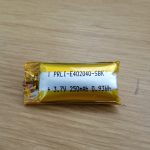
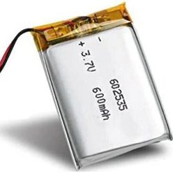
The batteries were the main thing. K8 use lithium batteries with 250mah power. I found some batteries online with a capacity of 600mah which I thought I could make fit (see below for details – not quite, but I made it work). I also bought a cool new charger for the new batteries.
The procedure
For anyone who wants to try and do this, I am posting some tips and photo’s.
1. Taking apart the club
Pull off the tape from the center, then pull out the staples:
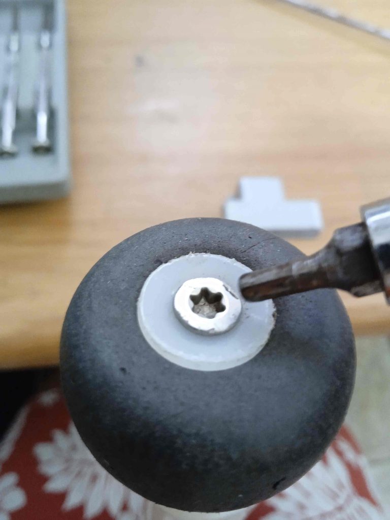
Take off the knob and top bumper:
Pull off the plastic around the handle, then unscrew the plastic spacer (needs an allen key)
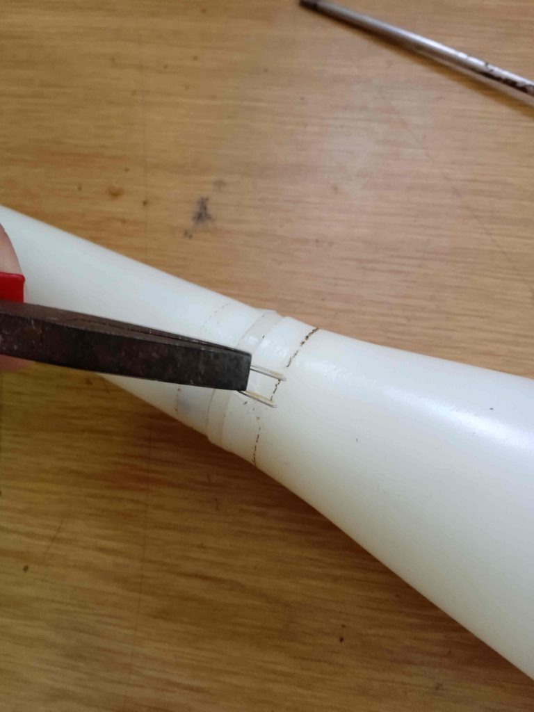
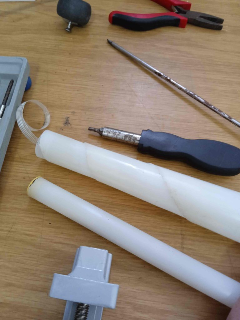
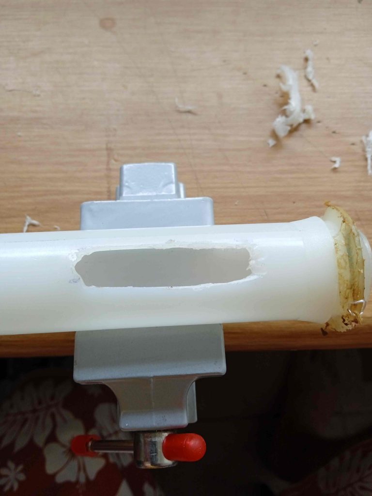
The next part is really sensitive – make holes in the top of the bulb cover to let the inside pipe come out. Get it out by pushing from the bottom – I also shoved a dowel inside and pushed upwards. If you use too much force this plastic pipe could bend, so be careful.
Now pull out some more screws holding the thicker top piece of the inside pipe on, and pull the spacer out to let the electronics out.
The bottom thin pipe should come off easily, leaving the bare circuit board.
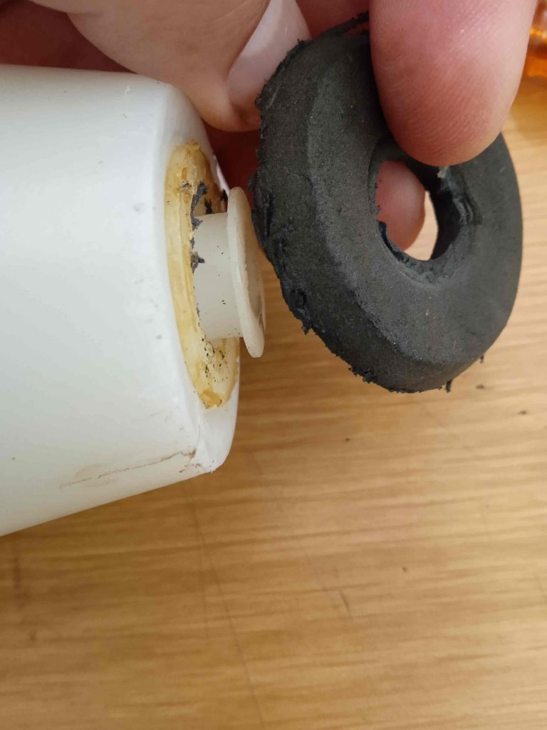
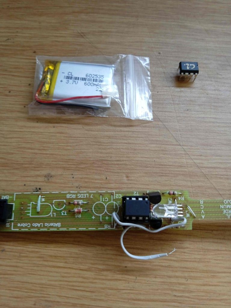
Now cut off the insulating cover, exposing the battery. See how fat it is!
Pull the battery away from the board (carefully) and cut the two wires as close as possible to the battery – we need those!
The new battery ready for placement. Also, my newly programmed chip in place (old one from K8 labelled C2.
Now comes the hard part. Making space for the new battery. I had to cut into the larger diameter tube on both sides so that this could fit. I actually bought a Dremel to do this job.
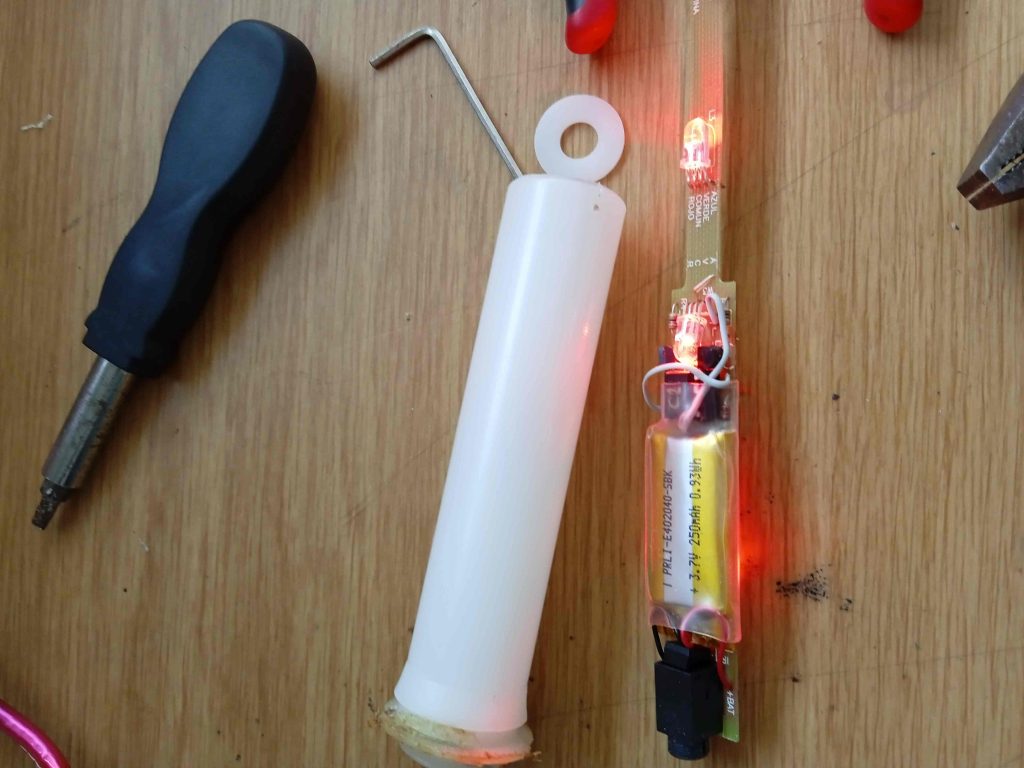
Now put the circuit back into the top pipe, and find the battery wires. Then solder the battery on – finishing with insulation. The battery should fit with only a little bit sticking out on both sides of the pipe.
I used clear tape to stick the battery in – it was already pretty snug as the holes were just right.
Putting it back together
Just like taking it apart, only in reverse (and much easier)
Put the longer circuit cover tube back in and line up the holes (with the spacer), then put the screws back in. This works fine with just pliers, just twist left and right for these, while pushing in firmly:
Now the inside tube goes back into the top of the bulb – it just snaps in easily (how hard was that to take out, though, whoah!)
After putting the top bumper back, the middle spacer goes on. I forgot to mention, that doesn’t come off without removing a plastic screw cover (yellow, bottom of thin tube) so keep that in mind if you haven’t taken this apart yet.
Finally it’s time for the wrapped plastic handle – I didn’t put the staples back, you are welcome to try and do that..
Add some tape to keep everything together, screw on the knob and your club is “as-new” again.
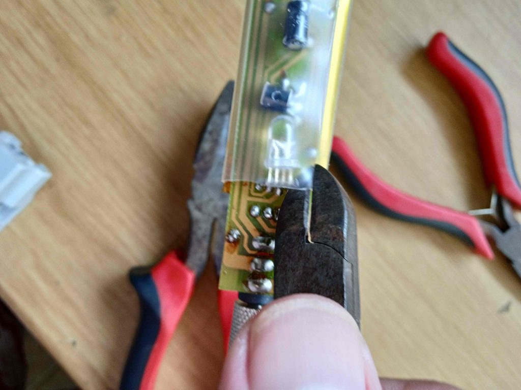
Just a quick tip, I noticed that there is a bit of wear where the circuit goes from thin to thick (you will see what I mean – the long bit with all of the LED’s. Some of my clubs had non-working colours due to this, and I had to bridge the gaps with wires.
Let me know if you have K8 clubs and are interested in upgrading yours, I am happy to answer any questions.
I love K8. Their reasonably priced LED equipment is the basis for my favourite solo juggling act, the “Electric Glow Juggling Show”. I bought my K8 clubs over 7 years ago, and last month they finally died.
Emergency!
Since the pandemic finished (or at least since we all learned to live with it) I have never been busier. People want to book my shows. Luckily, a friend has some working K8’s I can borrow for now, but long term I need to sort this out. I’m not changing manufacturer so the choice is to either purchase a new set or fix the ones I have. The pandemic also had the effect of limiting my finances for the past two years, so new purchases are on hold for now – so I opened up my K8’s to see what can be done.
Inside the K8 clubs and balls
First impression: these things are well put together. It took me the better part of an hour to get the electronics out without destroying the club in the process. I found the problem: a really fat lithium battery, completely finished.
Then I found something really interesting. The actual circuit is pretty straightforward and is running on a replaceable Attiny chip. So a few years ago I made some code for Arduino which was an attempt to emulate the K8 IR RGB internal workings. With a few adjustments this old code actually works inside of my favourite clubs – it was as simple as matching the alignment and dropping in my own chip. Thank you K8 for not soldering your chips on, and using a header instead!
The plan
First priority is to get the replacement batteries – I ordered these ones on Amazon: the same size as the original but bigger (>2x) capacity. Should be great if they work!
In the meantime I am working on the code, with upgrades such as variable strobe (like Aerotech equipment), and timed record and playback of settings for my show*.
*I understand that K8 have implemented a method of record and playback functionality in their latest equipment, as well as more new settings – if you need LED equipment I highly recommend going there and getting some. Also, their customer service is brilliant. https://k8malabares.com/
Here is a sneak preview of a new setting running on the bare circuit – Red/Blue with variable strobe!
If anyone is interested, the code is up on Github here – most of it is from many years ago and not very good, but I am working on it, need to have everything working without bugs by the time I receive the batteries. After I upgrade I don’t want to have to open the clubs again! When I get everything working I will do an “instructables” style tutorial – even if you aren’t interested in the firmware upgrade, the battery replacement is worth doing to extend the life of this amazing equipment. By the way, one of my K8 balls stopped working ages ago – I just opened it up and the battery is replaceable too!!
Current state of Magic Poi – and some ideas for the future.
First of all, an announcement: Magic Poi is now available for ESP32, as well as ESP8266 architecture. This will bring improvements in performance. I plan on continuing support for both, and in the near future a combined code base will be provided.
I am going to list current features here, and improvements I plan to implement.
On-board images:
I have partnered with EnterAction, an awesome Sydney based fabrication company who are taking over the hardware development from now on. Improvements will include an SD card add-on for limitless on-board storage. This will require changes to the code, as currently the maximum is 52 images supported.
UDP streaming:
this is a defining feature of Magic Poi. The images are generated off-device, and “streamed” via UDP pixel by pixel. I plan to keep improving this functionality but change it to not be the default mode. Due to WiFi interference the UDP stream is sometimes interrupted, making the LED’s stutter, so work is being done to mitigate that.
“Timeline” – images changing in time to music:
currently there is a desktop app to generate the timeline (and associated images) and save as a zip file, which needs to be uploaded to the Android app in order to be “streamed” to the poi. I plan on changing this functionality to rather happen in the poi code, thus avoiding the WiFi interference problem. The timeline editor will be made into a web app, with the option to download directly to the poi.
Station mode:
poi connected to a router provides more stable WiFi than the current AP mode. I have made a start on providing a way to use this mode.
Online account:
like a PlayStation or Kindle, there is a benefit to having a cloud aspect to any product that consumes media. The Magic Poi website is going to be a place where you can upload and share images and timelines, as well as interact with other poi owners. All uploaded images will be private of course, unless shared. I have made a start on this cloud aspect, with an option in testing to download images directly from your cloud account to the poi. The ultimate goal is to be able to sync any two pairs of poi with two clicks!
Android app:
Still not working: text to image (stream words directly to the poi).
Once the online portal is finished, this will be added to the app, so shared images and timelines can be viewed without need for a web browser.
The above is a small part of the list – thanks to EnterAction taking over the hardware development side, I will have more time to devote to the software improvements. We also plan on adding a battery level indicator, and a higher power battery for more play time.
Thanks for reading!
Keep an eye on this blog, and sign up to the newsletter (if you haven’t already) for more updates as Magic Poi moves forward towards it’s inevitable crowd funder launch!
Job hunting is tough – I’m busy until February 2022 but already feeling anxious about finding the next gig. That’s why I wanted to give myself a bit of an incentive – a visible indicator of success. I decided that whenever someone visits my portfolio site, I wanted an LED to light up. Read on to find out how I did it (using Flask, http requests, and an ESP8266)
Self Hosting
I recently had a bad experience with an online service shutting down on me – had a bit of a rant about it, although in the end it wasn’t too serious – but I am now determined to do self-hosting wherever possible *disclaimer: my current work project is hosted on Google Cloud, and I’m using Firebase and push services for some Android apps also.
The Flask api
The first step was to create a simple Flask api to facilitate tracking of site visits. This is based on this minimal flask api template on GitHub. I used a simple global variable to keep track of website visits because I’m doing this in my spare time and because it works fine – and I love boolean switches. Here is how it works in one simple gif:
Think of the hand as a visitor to my site, and the “switcher offer” is the ESP8266 at my home checking the api (the switch)
HTTP request from resume site
Since I am learning React my portfolio site was a good way to have another look at the framework. I used this single-page React resume site template as a base, adding my own details and an http request to the Flask api endpoint on load.
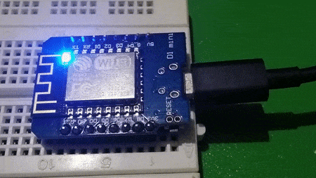
ESP8266 code
I used the basic http requests example with my own api details, and added in EEPROM code to record the incrementing number of visitors to persistent memory. The ESP8266 module checks once per second with the api whether there has been a new visitor to my site. If there has, the built in LED on my D1 Mini switches on. Although I have mostly moved over to using PlatformIO, for this very simple sketch I used the Arduino IDE.
Deployment
Like I said, this one is self-hosted. I’m using Digital Ocean droplets, which are a fixed cost of 5 dollars per month, for as many sites and services you can cram on there (trust me, it’s a lot). The React site was surprisingly simple to deploy, just build, copy the build folder and point Nginx at it. Flask is a little bit more complicated, compared to how easy it would be on Google Cloud, for example, but a few config files are really not too much to handle.
The result
Whenever someone visits my website, the LED lights up. Simple as that. And I can plug in and check how many visitors I have had. I’m hoping that one of those visitors will like what I do enough to hire me next year!
If I was making this into a product, I would certainly upgrade the Flask API to include a database to keep track of the number of visits, rather than doing this on the ESP8266 EEPROM – which maxes out at 255!* Obviously this could include a web interface for accessing the information, I could log the times… But most of this tracking stuff has been done already – analytics for websites. Perhaps the ESP8266 could pick up some of this information and display it on an LCD screen. A flask service for accessing Google Analytics from Arduino perhaps? Let me know if this is something you are interested in!
Also, proper authentication – if this wasn’t just for myself… JWT, rate limiting, CRUD endpoints and a web interface to change LED behaviour.
And maybe an RGB LED would be nice, then I could add in some of my other websites, in different colours!
*apparently the Arduino EEPROM library works differently on ESP8266 – ignore that part of the code, I need to update it (the counter still increments while the module is plugged in, though)
Now that I’ve had a chance to play with it for a bit, I really like VSCode a lot.
Here is my current setup for Arduino editing:
Added arduino-snippets plugin (autocompletes arduino code such as “millis()” or “loop()”
in c++ highlighting plugin (installed by default), disabled error squiggles
right click and open folder (the one with the .ino files in)
terminal (within VSCode)
arduino –upload main.ino
The above setup does require Arduino to be installed and set up separately. The upload command for example is part of arduino install and uses the last settings (board and com port for example) that you set inside Arduino IDE.
I still think I might move over to Platform.io eventually, but at least with this setup I don’t have to re-do all of my code.
My favorite practical Arduino project is getting a bit large for Arduino IDE, so I am looking to move the development over to a “real” IDE. During the past few months I have enjoyed using Visual Studio Code (on my laptop running Xubuntu) for HTML editing. Since they have plugins I thought I would give it a go.
First attempt: Platform.io
Platform.io has some impressive marketing out there. They also support esp8266 which for me is a must. Unfortunately it is another setup which requires an entire rewrite of the code (renaming all .ino files to .cpp for example) and for the amount of projects I have lying around and return to regularly that’s a definite pass. *UPDATE: unless there is no other choice!
Arduino Plugin:
There is a nice plugin for Arduino, however. It does require you to already have Arduino set up on your system (check). To set up the VSCode plugin you have to point it to the Arduino installation folder.
So far in testing the whole thing works, uploading sketches just the same as Arduino, except now I have tab completion(the IDE completes your commands for you when you press <TAB>) and advanced syntax highlighting. Best of all, VSCode comes with Dark Mode!
I think I might enjoy it, going forward. The only issue so far is that VSCode is no lightweight, it seems to be using a fair amount of resources to run. Nowhere near Android Studio, however.
*UPDATE: Unfortunately the Arduino plugin somehow fails to support multiple .ino files for an Arduino sketch (!!!!!). Here is the bug report: https://github.com/microsoft/vscode-arduino/issues/271
This is simply unusable as a result (sigh)
Guess I’m having another look at Platform.io – for lack of alternatives!
If you stumble upon this post and have a solution please send me an email tomjuggler at gmail dot com
PS I did try the alpha version of Arduino: Arduino Pro IDE https://www.arduino.cc/pro/software but it’s just that, alpha. 106 Errors in my code? But it still compiles and uploads fine?