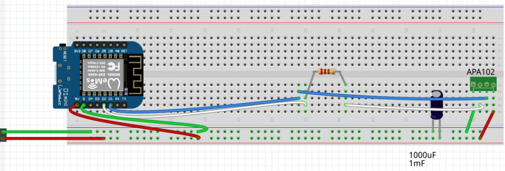
First things first, have you tried setting up the breadboard test circuit?
Does the SmartPoiOffline sketch upload correctly, and display on 36 connected LED’s? (if you have a longer strip and don’t want to cut it, that’s fine, the rest will just be blank)
Ok it’s time to try streaming pixels.
First load the SmartPoiBasicStreaming sketch to your microcontroller. Right now this is only being tested on the D1 mini, but should work on any ESP8266 board.
The SmartPoiBasicStreaming_UDP_Send program works on PC or Android, you just need Processing IDE with Android Mode installed if you want to do Android.
First, switch on the D1 Mini with LED strip attached. Wait for the led’s to finish cycling their startup pattern, then you need to use the wifi settings to connect the device (PC, Android*) which is running the processing code to the Smart_Poi_2 access point. The password is for this test is: “bluefire”.
*Note: since Marshmallow version, Android has had a nasty “captive portal” detection which refuses to connect to AP’s unless they are able to access the internet. I understand why they did this (security), but without root the only workaround is to put the device in Airplane mode, then switch on WiFi while still in Airplane mode, and connect from there. The annoying notification should be ignored, as there is an option to “never connect to this network” in there somewhere and it will trip you up. I should probably do a post about this. Just swipe it away, don’t click!!!
Once connected, start the program. Welcome to the world of streaming poi.
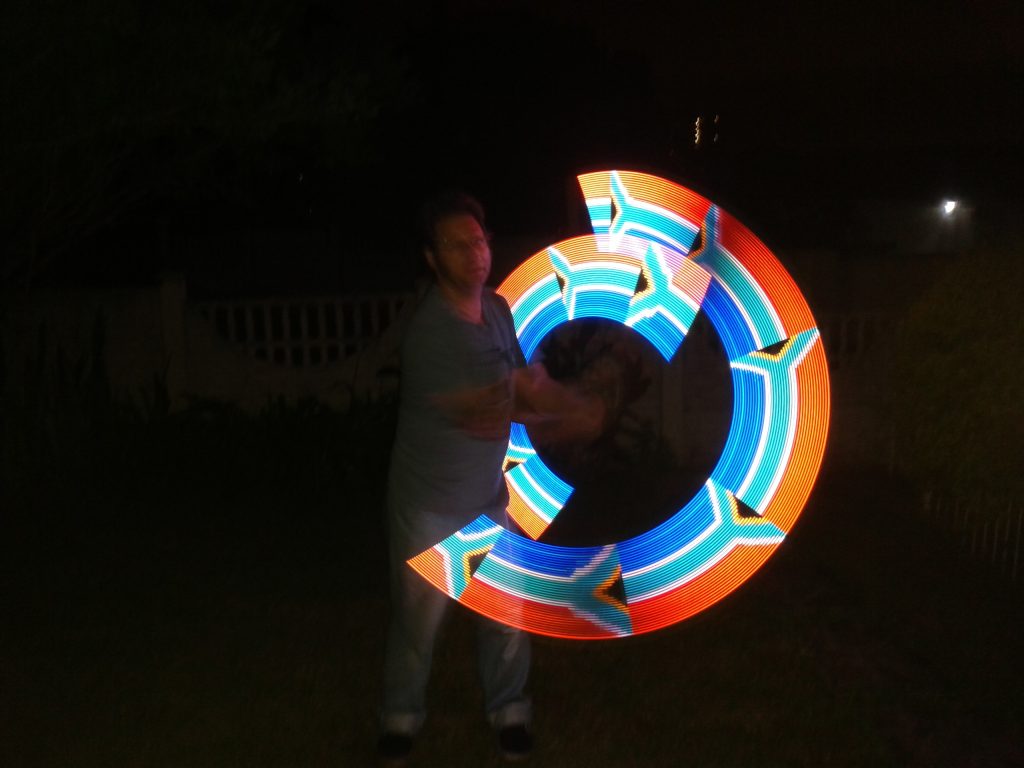
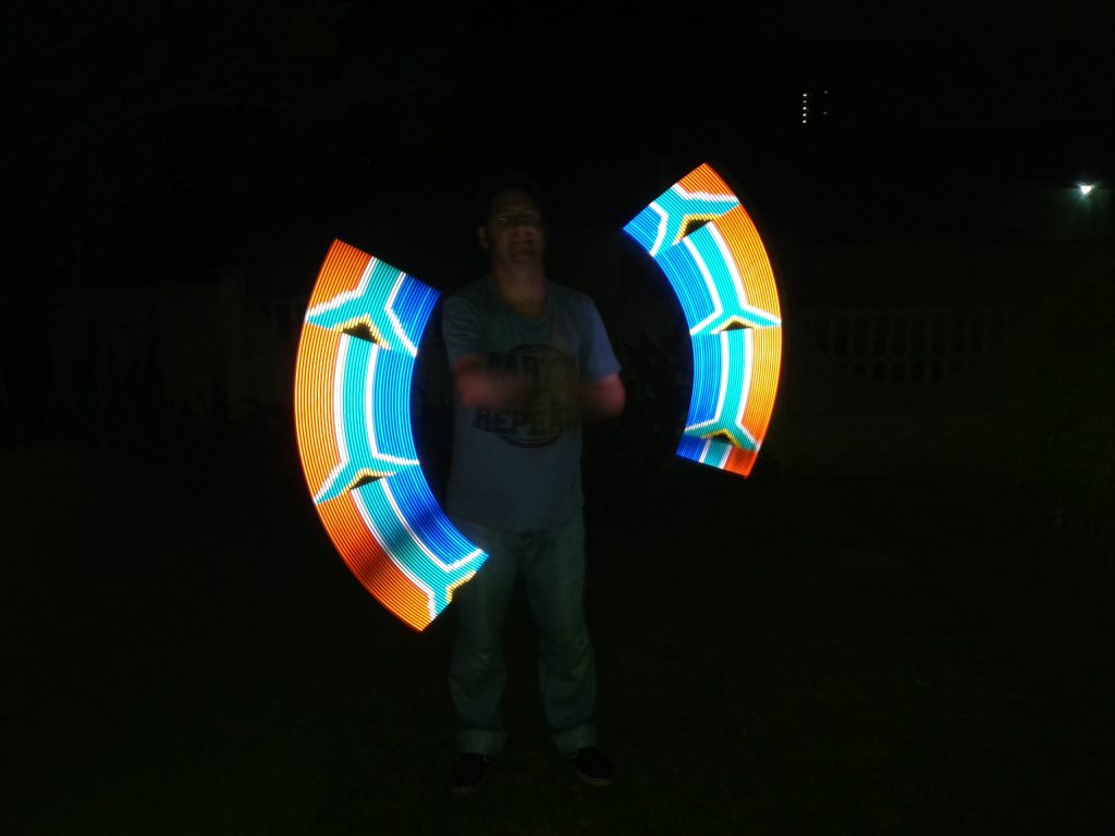
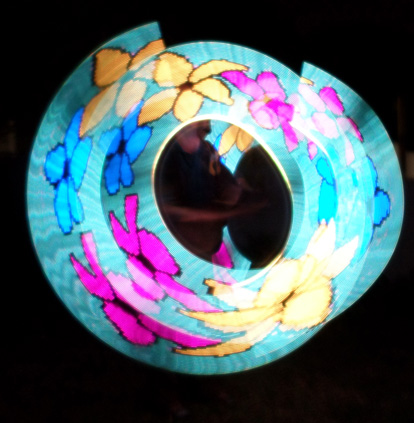
A couple of notes: the test program is not POV, it’s an animation (cylon effect) as this is easier to see on a breadboard. I have a complicated program to send images to the poi which are seen only when they are spun, however it’s easier right now to just start with a simple app for testing.
This program does demonstrate one advantage of streaming as opposed to rendering purely on the poi – that is control. It is trivial to change the colour from the random colours I have chosen to any you could wish. I had another version of this program with three knobs which can change the R, G, B values being sent. You could do a curve instead of straight lines, make the line fatter or thinner, slower, faster, and much more.
Have a go, and let me know what you think. Coming soon: more POV poi shenannigans!