k8 Clubs what are they and don’t they come with a remote already?

K8 prophecy clubs and balls come with their own remote, which controls all the colour settings. Why did I make another remote then?


Well, first of all, the clubs and balls may glow in the dark, but the remote certainly doesn’t*. The remote is very small and conveniently fits in a pocket, however it is virtually impossible to determine by feel which end is the business end. And by that I mean the end with the IR LED on, so that your hasty button presses actually have an effect… because as we all know, if you point the remote at the stereo, the tv will not change channels.

*Update: I wrote to K8 recently with regards to getting some new equipment, and it turns out their new remotes glow in the dark. They also have an awesome new record pattern function, to make changing colours easier. Can’t wait until I can afford the new K8’s!

Then there are the fiddly buttons, I have to admit my eyesight is not the best and I have broken too many pairs of expensive prescription glasses to hazard wearing them at my juggling gigs (juggling club to the face… it happens). So inevitably I end up squinting in low light trying to see which button does what, I quickly decided this was not the way I wanted my show to go.

Here is a shorter (low ceiling) version of my show running from an IR dongle, on a laptop, synchronized with some DMX lights via midi. Super complicated setup, I gave up on this after a couple of years of doing it. I needed an easier way…

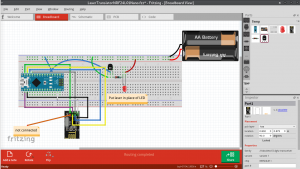
Introducing the ONE button remote.

How does this work? One very prominent button, when held down will repeatedly send the correct signal for my equipment at the time I am pressing it. Once pressed, the program increments to the next required signal and that one is sent on the next button press.

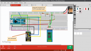
One button, many signals. So now, in my show I occasionally hold up a remote and change the program on my IR juggling toys. I don’t need to be able to see the remote in order to do this, finding the remote takes no time (it’s tied to my homemade juggling equipment stand) and the button is big and can be found in the dark. Also the signal of MY remote is quite a bit boosted from the k8 version.

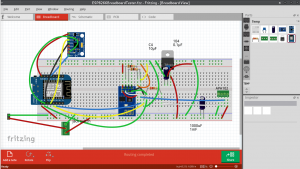
Here is an arduino sketch which demonstrates the principle (without the IR, I will share the k8 codes if anyone is interested).

EepromOnOffLedExample

Simply put, there is a number saved in EEPROM. Every time the Arduino boots up, the number is incremented, and saved again in EEPROM. The saved number corresponds to an IR signal. Thus a different signal each time. I make sure to loop the number back to 0 again of course at some point, otherwise the EEPROM register will overflow, blowing up the Arduino in the process I imagine 😛


Smartpoi is open source

I am working towards opening up the whole thing, hopefully I can get some productive feedback this way. However, to make something for yourself is one thing, to share is another. Lets just say the code is not ready to be shared. #messyprogrammer a lot

In the meantime here is a simple POV example on github which will work for esp8266 connected to an APA102 144 strip (36 LED’s only for testing). Don’t forget to add a cap between +5v and GND.

SmartPoiOffline

Here is a test board I made up, you don’t need the whole lot, just one of the esp breakouts and the LED strip. Here I have 2 controllers (only one on at a time!) and also a voltage regulator, and accelerometer as well.

In case you are wondering, the Esp-01 is connected to the breadboard by this method: http://www.instructables.com/id/Making-ESP8266-01-module-breadboard-friendly/

Simply put, you remove the plastic pin spacers with plyers, and now the pins are bendable to a more breadboard friendly configuration. No soldering needed.

Breadboarding Stage

Test breadboards finished, populated and tested working (with LED’s) here.

First the RF controlled laser (nRF24L01+). couldn’t find any lasers in Fritzing parts 🙂

We plan on controlling more than 10 lasers, so made 4 of these on breadboard for the software test:


Next up is the Bluetooth Controller. This pairs via bluetooth to an Android app which then sends the correct on/off signal via RF to the Lasers.

Currently the signal is sent to all the lasers simultaneously, then they work who it was for according to what was sent. The signal is actually sending RGB codes, in case I want to add RGB in later, so should look like this: 1 255 0 0 means laser number 1 is on (or RGB led set to RED 255 full on).

1 0 0 0 would mean laser 1 off. The last 2 numbers are redundant but I am hoping to re-use the code for RGB LED’s at some point, so a couple of wasted bytes is nothing.


Speaking of wasted bytes, there is another byte for the node (the RF24 Arduino library uses the concept of nodes – up to 6 connected to each signaller)

I wanted to have more than 6 lasers and noticed if you define 2 nodes with the same address they both receive the signal. I am pretty sure that if 100 lasers are defined with the same node address they will still all receive the same signal. Then the software I have written can distinguish which laser is supposed to turn on, by parsing the 2nd argument. I am keeping the node byte for possible multi-setups.

Here is the full transmitted protocol:

Node

Laser

Red

Green

Blue

– using RED value for on/off on the one laser I have connected on the receiver side.

-soon we will have multi-lasers!

Android Development Overview

For Android I started off using MIT’s app inventor:

http://ai2.appinventor.mit.edu/

This was fun and I had some success with a few projects, however as a touch typist I am always more comfortable using the keyboard. As I was already using the amazing Processing IDE for desktop Java apps,  Processing for Android was the next step:

https://processing.org/

Of course there is no substitute for the real thing, which is what I am using most often now, Android Studio. Processing for Android provides a handy tool for exporting sketches as they are called, so the transistion is pretty seamless. Android Studio is a huge IDE with bells, whistles, mags and stickers attached. Learning how to use this beast is going to take a long time, especially with Google pulling out the rug (ie changing everything with each new release) every couple of months.


ESP8266 Overview

What can I say about the ESP8266? It’s cheap, powerful and I use it to stream images from my phone to my Smart POV Poi.

Currently I am using the ESP-01 version (above) – I connect the esp-01 to the breadboard by this simple hack:

http://www.instructables.com/id/Making-ESP8266-01-module-breadboard-friendly/

I also use the very capable D1 Mini for development (below).

The code is all Arduino, with FastLED library for led driving. The only issue with ESP8266 is power consumption, the wifi uses far more power than the Atmega328 for example, however compared to the LED strips (144 LED’s at once) it is negligible.