“Vibe Coding” is the new thing – I consider myself a proponent of it. Coming from my “Copy Paste from StackOverflow” style it was a natural fit.
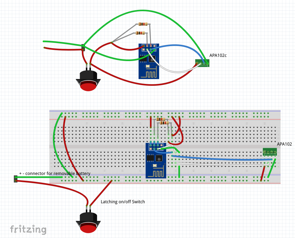
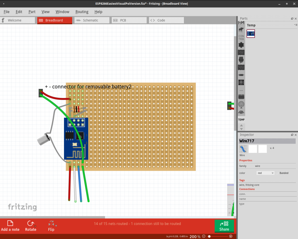
Having said that, I still (mostly) try to read the code. Sometimes you have to – especially in PlatformIO. AI simply doesn’t work as well for embedded code – probably because a lot of the good stuff is proprietary and not available to LLM scraping. Less code means less effective models. That ends up being a bit of a hassle when trying to do the code – test – fix loop. First of all it’s actually code – upload – monitor – test – fix if you are working with microcontrollers (never mind ones with web servers running, or interacting with web servers and apps!).
Simply put, I waste a lot of time waiting for the AI to finish coding so I can run a command or press a button to upload and check something.
Introducing Cline
Cline is an open source VSCode AI extension that works with open source models (you can also pay for a better experience). It can edit multiple files at once, run commands and interface with MCP servers! That’s all I needed for my test.
In the video below I show how you can easily get AI to do the coding loop for you – automating the boring stuff, as well as writing the code. For this test I actually went with the FREE version of DeepSeek 8B, which apparently can run on your own GPU (I don’t have one, so I’m using OpenRouter here).
This is a pattern that I plan on building on in the future. I show how to add a file with commands for Cline to run (upload, monitor) and how I bring it all together with one big prompt so that Cline actually runs everything on its own!
Future plans
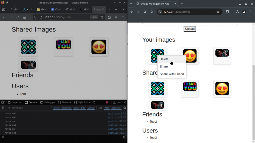
I have also done something similar with the puppeteer MCP to automate browser testing. I run an embedded server on an ESP32 with automated embedded coding and monitoring – and puppeteer to do button clicking after code changes to test everything works. I should make a video about that.
I still have to make a big instruction file for Cline – with all of the ideas here inside. Then hopefully I can just tell it to make me a project in full and it will do it (beware, Cline seems to suck up tokens really fast!)
I do want to add Aider as an MCP for the coding part, though. Aider still has a lot of advantages, especially it’s git integration and configurability (maybe I’m just used to it). Hopefully the MCP option can seamlessly integrate with normal use (same config files and history?), I haven’t looked yet.
Also, I’m not very good at this part, but debugging is important – sometimes it’s essential. I would love to automate the debugging part, using AI. Maybe a PlatformIO debugging MCP server? We don’t have one yet…