So I have been working on the vervet monkey detector idea for a little while now. So far I have had some success with the back end. Here is an update on how it works so far. (tldr I used Google Cloud Vision api and some bash scripts)
1. I take a photo of the monkey (I still need to automate this, with motion detection)
2. Upload to my server using scp
3. Some moving around on the server to make the image public for Google Cloud Vision to see it – using inotifywait and mv
4. Google cloud vision api call with image url using curl
5. To do: parse json response from google to check if a monkey is actually there.
6. Send a signal to wireless valve (switches on the sprinkler and hopefully gives the monkeys a fright) – I have built one already, just need to modify the code slightly for wireless. Thinking of using esp8266 for this, since I have so many lying around, and a 12v battery since the tap valve solenoid runs off of 12v. I have a nice circuit board I built for my wireless poi which incorporates an ESP-01 and a voltage regulator. Add in a relay to switch 12v and it’s done.
So there is much to do. There is also the question of accuracy, obviously I don’t want any false positives wetting any unwary visitors, so I need to test this a lot before using it. The first version will trigger an alarm only, which in itself could be useful as a phone app, for example. We might be able to leave the windows open on occasion, with a monkey detector to alert us when one tries to get in and steal our food (this happened twice in the last week)
At some point I will have to make my own machine learning classifier for monkey images, as Google charges $1.50 currently per 1000 images classified. The first 1000 are free, but they have a habit of changing the pricing on their products without notice.
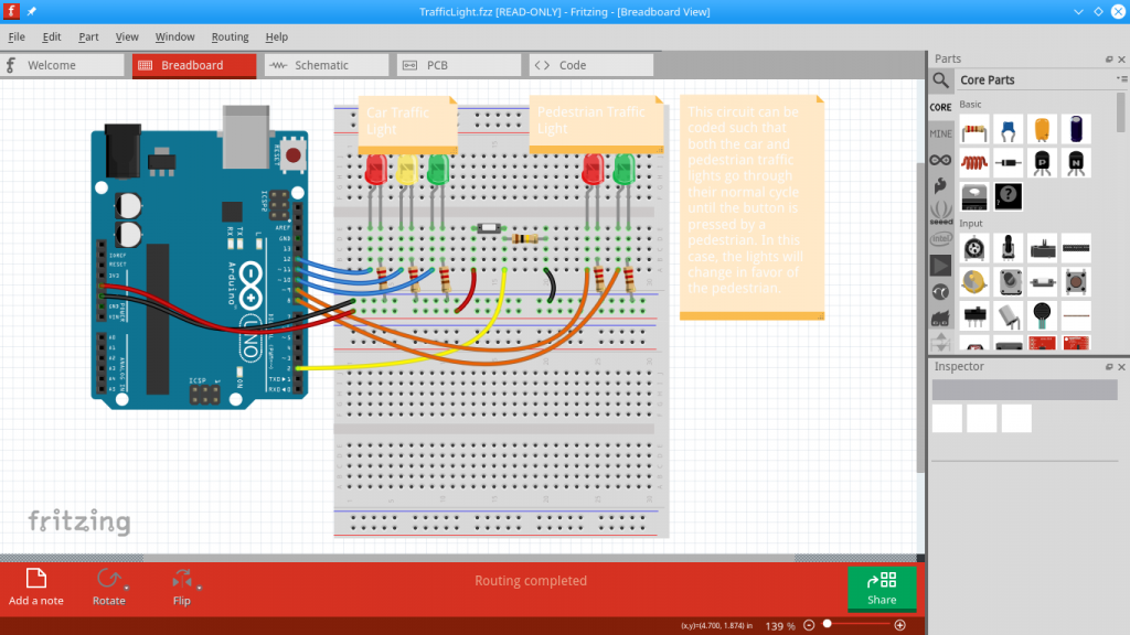
Fritzing is a great open source project. It turns out that plugging wires into a breadboard is a great way for 5 year olds to develop hand-eye co-ordination, so I have started making some kid-friendly projects for my son.
The first was a traffic light project. This is conveniently located in the Fritzing examples, although you have to go to their website (link) to get the Arduino code. They use an Uno as controller, but I prefer the breadboard-friendly Nano. I didn’t have to make any modifications to this project for it to be fun, apart from using the Nano instead of the Uno in the screenshot, and adding a blue LED with a separate switch, as my son insisted on having his favorite colour represented.
This project offered multiple opportunities for learning. For one, it’s a working traffic light, so we went over the rules with some of his lego characters, look before you cross, press the button and wait, etc. Secondly I left the jumper wires to my son to plug into the board, and tried to explain a bit about DC current as well. We had fun turning the LED’s the wrong way, I just made sure the board wasn’t powered when he was busy plugging things in.
For power I used a power bank, plugged into the nano with USB. The power bank has two outputs, so we can have two projects powered at the same time. There are quite a few projects which are fun for kids, and since my kid loves “helping his dad” it’s going to be something I will be doing a lot in the future. More to come soon.
Just wanted to mention a couple of projects in the pipeline for 2019.
I recently moved house and it’s a great opportunity to look at home security. In South Africa this is quite an important topic. Most homes here have burglar guards but while these may go some way to delaying an intruder they are by no means fool proof. An alarm provides an added layer of protection, especially if you are asleep, or not at home. The cheapest alarm I could find cost R2000 (around $150) but all it does is blare a siren. For a proper system which will alert you it’s significantly more pricey.
Of course I have so many microcontrollers around so I have started looking at the options of making my own super secure system. A friend has made his using an Arduino Uno connected to magnetic switches on the doors and windows. A GSM module provides connectivity, so both he and his security company receive SMS alerts if an intruder gains access. The whole thing is one long circuit with wires connecting every switch (this is true of many commercial home alarm setups as well) and each “zone” can be bypassed or set by sending an SMS code.
I made him an Android application to send the codes so that he doesn’t have to type them in manually any more but with my system I am hoping to eliminate the wires entirely as well. Not sure yet about the GSM module, SMS cost more and you need a dedicated SIM card (also I don’t have one and would have to order).
So it’s wireless, ESP8266 to be exact. I have been looking at mesh networks (the wifi doesn’t quite extend to every corner of the house) and have settled on painlessMesh as the best one. Each node in the network will consist of one ESP-01 connected to a battery and some sort of spring switch (or possibly a tilt switch) which will be turned on by the opening of a door or window. As soon as it is turned on, the node will send a message, alerting the main (always on) node that something has happened, possibly triggering the alarm (and sending me an SMS, email or some other notification). This way the battery is not draining all day, only when it is needed.
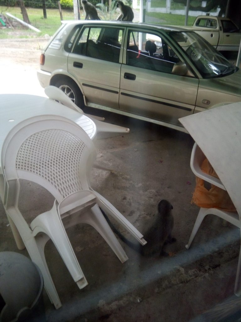
The other problem at my new place is a bit more novel, we have a monkey problem. Situated near a nature reserve the birds and butterflies are prolific but Vervet Monkeys come in and poke through our trash on a daily basis. I found a manual method at https://www.wikihow.com/Repel-Monkeys-from-Residential-Areas – just tie your bin shut with slinky cables but the monkeys are so brazen, they steal our bananas from inside the kitchen as well. Basically as soon as you hear them it’s total lockdown, shut all the doors and windows and with the heat here that’s not great.
Image below: Monkeys on my car. One of them took a dump up there, which was the last straw for me.
My plan is to leverage Google’s Cloud Vision API to assist here. The image recognition works great for monkey detection (try it yourself here: https://cloud.google.com/vision/) – I upload a still from a webcam if motion is detected and then Google will tell me if a monkey is present. If one is, on come the sprinklers. The garden gets watered and the monkey runs away. Vervets hate getting wet, we have water squirters stationed at each entrance.
The only issue is Google’s pricing, it’s $1.50 per 1000 images scanned (after the first 1000 per month free). Ideally I would be creating my own recognizer with Tensorflow and using that but my CPU can’t handle this currently. Not to mention the time it takes. So Google it is. For now.
So.. lots to do, much code to write. Let me know what you think, if you have anything similar to share, or ideas for me to try.
I emailed my favorite visual poi graphic artist, Axel Belhache and he agreed to let me use his images in my shows. Here is an online animation showcasing his amazing work. You can click on the animation to advance to the next image.
There are two .apk files included in the zip file (4mb). In order for the app to work correctly you need to install and run “Smart Poi Setup.apk” – it creates the necessary folders inside the “Pictures” directory on your device. You may need to run this twice, depending on your Android version (file access permissions may only work the second time) – just check if WirelessSmartPoi and WirlessSmartPoi72px folders have pics inside or the main app will not work correctly. Smart Poi Setup.apk can then be uninstalled.
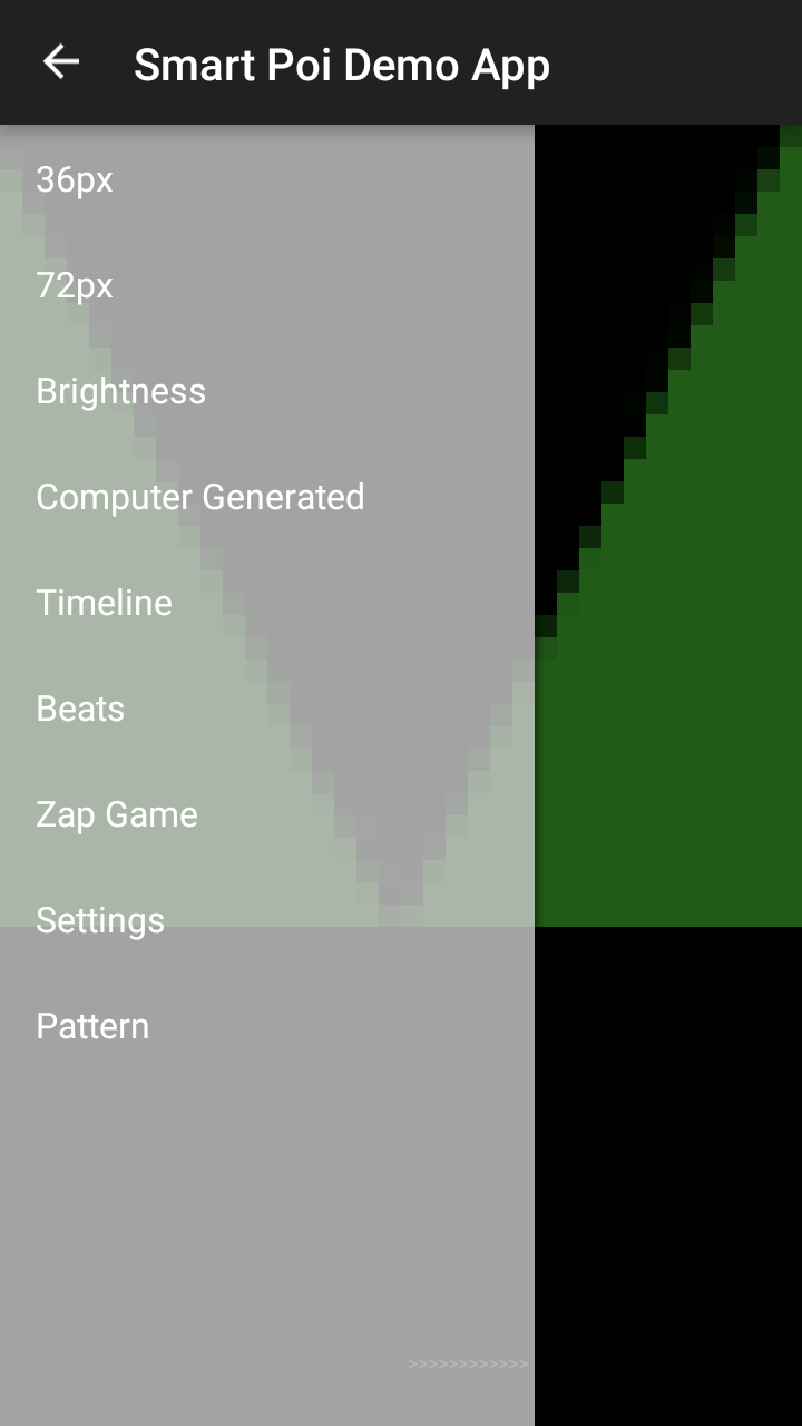
The second “Smart Poi Demo.apk” is a test app to show the capabilities of the poi. This version of the app is for anyone demonstration purposes only, the UDP send is disabled and visualization enabled. In other words it does everything but send signals to the poi. This is because my app slows down function if no poi is connected, trying to send to nowhere. You may need to be connected to WiFi for this to work, I haven’t checked if that check is still in place.
The Timeline option won’t work on this demo unfortunately as it requires a zip file created by the Timeline creator desktop program which isn’t quite ready for sharing. To see what the other options are meant to do on the poi check out my post here:
Anyway, have a look and let me know what you think! So far tested working on Android KitKat through to Nougat. Please note all images need to be rotated 90 degrees to the right for the app to work correctly. One day I will fix this..
I will be uploading the full app to the Play Store once the Poi Arduino code is ready for sharing. The ultimate goal is of course to enable anyone to make a set of affordable Wireless Streaming Smart Poi of their own, and hopefully find some programmers interested enough to contribute to the development of this project.
Some images from one of my poi spinning gigs, animated to show how they look on the poi. I am hoping to be able to make this into a service for other poi spinners, so they too can showcase their work. All images copyright Nu Metro Cinemas, adapted for poi by my talented wife, Amanda Hastings.
This is a bit old now, I have integrated all the functionality shown here into one large app since, however the video does give a good idea of the functionality.
When spun in this video, the poi look choppy due to the low frame rate. Please take my word for it, they look a lot better in real life. I have a better looking video of both sizes of poi being spun here:
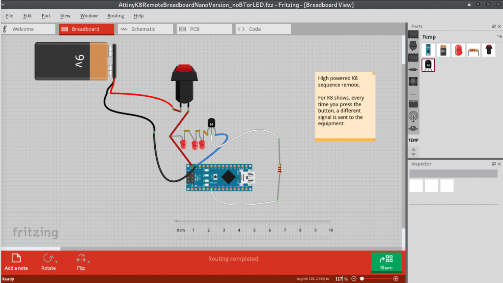
This is a post for K8 juggling equipment owners who are also into electronics. If you haven’t already read it, here is here is why I made my own K8 IR remote.
The circuit is quite simple. A 9v battery powers the Nano via Vin pin. A transistor receives output from the Nano, and this triggers a large current in the 3 connected infrared LED’s. The reason for the transistor is to maximize the signal, output of Arduino is only 5v but we need more for better signal range. You may notice that there is no resistor on the LED’s. IR pulses are extremely short ON/OFF pulses and so are not likely to blow up the LED’s in this implementation. I did have one connected previously but the range suffered.
I made a fun web program to demonstrate the functionality, you can see it here:
The demo works best on PC but you can see it on a mobile.
How to use it: click on some of the remote buttons, then press the big grey square at the bottom right to start (scroll down/across if you can’t see it). Press the bottom right square again to cycle through the saved patterns.
Refresh the page if you want to try again. Some of the buttons are not implemented yet (eg. Demo)
My favorite is probably fade, followed by no. 5 which is my favorite K8 pattern anyway.
This transmitter (at least with the IR LED’s I have) is more powerful than the K8 remote I received from them.
The code I will post in another article, however it is really simple, while the button is being pressed, the saved signal is sent, once per second (not more – one of my K8 balls has stopped receiving I believe due to too many signals sent*)
Stop pressing the button and the remote is off (saving battery of course) and next time the signal will be a different one, depending on the program.
*I am not a K8 engineer but their equipment stores the last pattern in memory. I believe that a piece of EEProm memory is overwritten each time the signal is received, so take care to not send too many signals, or your equipment may stop working. On Arduino chips EEProm memory is rated for 100 000 rewrites, obviously this is a minimum but evidently I exceeded this in some experiments.